TORSION DIAGNOSTIC SYSTEM UTILIZING NONINVASIVE BIOFEEDBACK SIGNALS BETWEEN THE OPERATOR, THE PATIENT AND THE CENTRAL PROCESSING AND TELEMETRY UNIT (United States Patent)


Physical basics of informational interaction
-47-
Torsion diagnostic system utilizing
noninvasive biofeedback signals between
the operator, the patient and the central
processing and telemetry unit
United States Patent 6,549,805
Nesterov et al. Apr. 15, 2003
ABSTRACT
BACKGROUND OF THE INVENTION
The present invention relates generally to a
biofeedback medical diagnostic system. More particularly,
the system of the invention utilizes remote
noninvasive biofeedback signal between the operator,
the patient, and the CPT (central processing and telemetry)
device to determine a pathological condition
of the patient. The biofeedback signal is generated
subconsciously and is based on device enhanced
intuition.
A variety of medical diagnostic systems are
known in the art to determine the patho-physiological
status of the patient in general and to diagnose a
variety of ailments and their state of progression. A
simple example of such a system is a visual diagnostic
device based on critical fusion frequency such as described
in the U.S- Pat. No. 6,129,436 by Treskov or
the Russian Patents No. 339,280 and 1,076,087. In a
self-administered test, the patient can gradually increase
the frequency of a blinking light until the point
of fusion is reached and the patient is unable to distinguish
between individual bursts of light. The frequency
of that fusion is indicative of the state of the
patient’s nervous system and can be tracked over time
to monitor its changes. An improvement is described
in the Russian Patent No. 814,337 wherein the test
is administered before and after a physical exercise.
Such systems have generally limited ability to indicate
the variety of patient’s conditions due to the fact
that only a part of the nervous system responsible for
processing a visual stimulus is involved with the test.
Such complex phenomenon as a change in working
ability or the state of tiredness of a patient frequently
results from other changes in the nervous system that
would go undetected by such a device.
The situation of playing a dynamic game is used
in various psycho-physiological evaluation devices to
determine the state of a variety of body functions. Examples
include such functions as attention, memory
and vision (Russian Patent No. 825,001); sensing
and motor reactions (Russian Patent No. 850,043);
ability to choose (Russian Patent No. 929,060); the
function of following a moving object (Russian Patent
No. 827,029); ability to find the ways out of the
difficult situation (Russian Patent No. 878,258) and
even the predictive abilities (Russian Patent No. 839,
488).
A more comprehensive biofeedback device is described
by Schweizer in the U.S. Pat. No. 4,195,626
and includes application of a variety of audible, visual,
electrical or tactile stimuli in a specially designed
biofeedback chamber. Moreover, a microprocessor -48-Physical basics of informational interaction
-49-
controlled rhythmical pattern of these stimuli is proposed
and is adjusted based on the patient’s own reactions.
Ross et al. in the U.S. Pat. No. 4,690,142 suggests
electro-neurological stimulation of specifically
described places on the skin of the patient. Production
of such tactile stimulation of the skin is used to
generate electrical characteristics of the organism responsive
to a particular condi-tion. The system of the
invention is also used to train the organism to change
its reaction to the stimuli by concentrating on increasing
or inhibiting the tactile sensation.
An even more sophisticated system involves detecting
the patient’s electrical brainwaves via electroencephalogram
or EEG as measured from a number
of electrodes attached to the patient’s scalp. Several
examples of EEG based biofeedback devices are
worth mentioning here among a large number of such
systems described in the prior art.
A multiple channel biofeedback .computer is described
in the U.S. Pal. No. 4,031,883 by Fehmi et
al. which contains a number of monopolar electrical
contacts applied to the scalp and the body of the patient
and a computer for collecting, filtering and amplifying
the electrical signals therefrom. The overall
feedback signal is then presented back to the patient
to create awareness of the function being monitored
of for other purposes.
Ross et al. in the U.S. Pat. No. 4,800,893 describes
a kinesthetic physical movement display in
which a number of electrodes feed their respective
signals to an EEG apparatus equipped with a video
display. Generation of kinesthetic physical movements
allows the user to produce desired thought
patterns.
A method for treating a patient using an EEG
feedback is described by Ochs in the U.S. Pat. No.
5,365,939 and involves selecting a reference site for
determining a brainwave frequency and entraining it
in both directions until a predetermined stop point
is reached. Flexibility assessment is then conducted
with respect to the ability of the patient to change the
brainwave frequency.
A method and device for interpreting concepts
and conceptual thoughts from a brainwave date of a
patient and for assisting in diagnosis of a brainwave
dysfunction is described is proposed by Hudspeth in
the U.S. Pat. No. 5,392,788. A system is described to
include a transducer for transmitting a stimuli to the
patient, EEG transducers for recording brainwave
signals, and a computer to control signal presentation,
EEG signal recording and analysis. A comparison
is made between the recorded EEG signals and
a model of conceptual perceptional and emotional
thought or as an alternative to the known EEG signals
from healthy individuals to diagnose a brain dysfunction.
A method for determining the intensity of focused
attention is proposed by Cowan et al. in the
U.S. Pat. No. 5,983,129 and includes obtaining a
frontal lobe brainwave EEG signal and subtracting it
from a separately obtained reference EEG signal to
produce the attention indicator signal.
Finally, an electroencephalograph based biofeedback
system is described by Freer in the U.S.
Pat. No. 6,097,981 in which a computer animation is
maintained by the computer and presented to the patient
while EEG response signals are simultaneously
being obtained and analyzed. Results of the analysis
are then used to control the animation. A provision
is made to send the EEG signals from the head of
the patient or user to the machine by remote infrared
transmitter.
All the above systems suffer from a number of
common limitations, which stem from their dependence
on the conscious state of mind of the patient.
Another limitation is that the patient himself is used
to interpret the biofeedback signal rather then an independent
entity such as an operator. Finally, hardware
is used to obtain the EEG signals and transmit it
via a wire or infrared method to the main data collection
and computing apparatus.
One further improvement in the accuracy of biofeedback
analysis is described in the Russian Patent
No. 759,092 in which various biofeedback signals
are assigned a certain value of relative weight by a
dedicated designation unit acting based on individual
characteristics of each patient or a test subject. Varying
these weight factors allows the apparatus to customize
the results of analysis for each individual user.
The use of magnetic and electromagnetic fields
is also known in the art to remotely and non-invasively
assess certain conditions of a patient or to influence
his state of fatigue and abilities to perform
certain functions.
Farmer et al. has described a device for monitoring
a magnetic field emanating from an organism
in the U.S. Pat. No. 5,458.142. It includes a magnetic
field sensor containing a ferromagnetic core
surrounded by a multi-turn fine wire. The sensor is
used to record the magnetic fields of an organism
for diagnostic purposes as well as to control a magnetic
field generator in order to produce a therapeutic
magnetic field complimentary to that of an
organism.
A bio-magnetic analytical system is described
by Zanakis et al. in the U.S. Pat. No. 4,951,674 and
includes a number of fiber-optic magnetic sensors
to obtain information about the magnetic field from
various tissues in the body including the brain.-50-
A device for influencing an organism is proposed
by Hein in the U.S. Pat. No. 5,108,361 and involves
exposing the patient to a number of short pulsed signals
supplied with increasing or decreasing frequency
to stimulate the cerebral waves.
U.S. Pat. No. 5,769,878 by Kamei suggests a
device for non-invasive enhancing the immuno-surveillance
capacity of a person by supplying a pulsed
light to his forehead (while shielding the eyes) in the
frequency range between 0.5 to 13 Hz and preferably
in the frequency of the alpha wave band as measured
from the EEG signals.
Finally, our Russian Patent No. 2,342,826 describes
a method and device for increasing non-invasively
the accuracy and output of an operator of a
bio-location device by using a low frequency unipolar
magnetic field.
The need therefore exists for a non-invasive diagnostic
system excluding the conscious influence of
the patient and his own interpretation of the biofeedback
signal.
SUMMARY OF THE INVENTION
Accordingly, it is an object of the present invention
to overcome these and other drawbacks of the
prior art by providing a novel non-invasive diagnostic
system using a central processing and telemetry
device and an operator to interpret the biofeedback
signal from the patient.
It is another object of the present invention to
provide a diagnostic system capable of processing the
biofeedback from both the patient and the operator.
It is a further object of the present invention to
provide a diagnostic system in which the biofeedback
from the patient is collected non-invasively.
It is yet a further object of the present invention
to provide a diagnostic system in which a device is
provided to enhance the intuition of the patient to facilitate
the formation of the biofeedback signal from
to the patient to the apparatus.
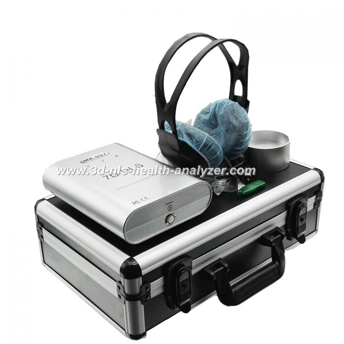
The diagnostic system of the invention includes a
central processing and telemetry (CPT) device capable
of providing a predetermined series of stimuli to
both the operator and the patient. Such stimuli can
be chosen of various types depending on the purpose
of evaluation. They can be of optical (such as a screen
of a monitor, a series of light diodes, etc.), sound (via
headsets or speakers), or magnetic nature. A triggering
sensor facilitates the biofeedback formation and
transmittal from the patient to the CPT device via
an analog-to-digital converter. Another biofeedback
loop is formed in parallel between the operator and
the patient. It is therefore the operator who is actively
participating in the evaluation and interprets its results.
To further increase the ability of the patient
to intuitively cause the triggering sensor to send the
feedback signal, a device called «cadistor» provides
an intuition enhancement. This devise subjects the
patient to a series of small level energy bursts with
the 5 frequency preferably coinciding with the theta
rhythm of the patient’s brainwaves.
BRIEF DESCRIPTION
OF THE DRAWINGS
A more complete appreciation of the subject
matter of the present invention and the various advantages
thereof can be realized by reference to the
following detailed description in which reference is
made to the accompanying drawings in which:
FIG. 1 is a general block-diagram of the diagnostic
system of the present invention, and
FIG. 2 is a general block-diagram of the triggering
sensor of the diagnostic system.
DETAILED DESCRIPTION OF THE
PREFERRED EMBODIMENT OF THE
INVENTION
A detailed description of the present invention
follows with reference to accompanying drawings in
which like elements are indicated by like ference letters
and numerals. FIG. 1 shows the main block-diagram
of the proposed system of the present invention.
FIG. 1
A CPT device 10 contains a situation-generating
block designed to output a predetermined series of
stimuli, also called «information codes» and transmits
it through a dual peripheral device to both the
operator 20 and the patient 30 (shown as dotted lines
on FIG. 1). A number of appropriate peripheral devices
can be employed with the system depending
on the nature of the information code. Examples of
such peripheral device include but not limited to: a
magnetic induction coil for modulated magnetic field
transmission, headsets or speakers for audio trans-Physical basics of informational interaction
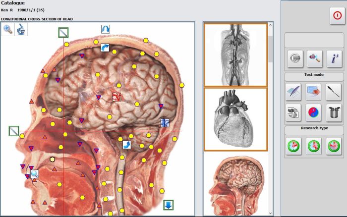
-51-
mission, video monitor or a light display for visual
signal transmission such as an image of the evaluated
organ for example, etc. It is essential to point out that
such information codes are transmitted to both the
operator 20 and the patient 30, a unique feature of
the diagnostic system of the invention.
A triggering sensor 40 collects the biological response
from the patient 30 as an analog signal (solid
line on FIG. 1), converts it into a digital one and
sends it back to the CPT unit (dash-and-dot line on
FIG. 1) as will be described in more detail below. The
CPT unit is also equipped with the designation block
for assigning specific relative weights in the input
signals from the sensor 40 depending on individual
characteristics of the patient.
Cadistor 50 is designed to work directly with the
patient 30 to facilitate the work of the triggering sensor
40. It consists of a silicon-based semi-conductive
transistor crystal acting as optoelectronic radioelement
when illuminated by a light source such as a
laser. Preferably, a silicon field-effect transistor is
used in which a control area is in the form of a thin
flat channel. When a laser light is directed at cadistor,
an abrupt temporary short circuit is formed in the
semiconductor and a small level of energy is released.
Repeating of that process with high frequency caused
periodic releases and accumulation of the energy. It
has been established that the preferred wavelength of
laser light is between 630 and 680 nanometers, the
laser power should be below 5 MW and most importantly
the light pulsation has to coincide with the
theta-rhythm of the patient’s brainwaves.
The cadistor is placed on the forehead of the
patient about 1/2 of an inch above the nose and the
eyes and symmetrical there between. Appropriate eye
shielding and other precautions are recommended to
avoid damage by the laser. The laser source is located
only about 5-6 inches from the patient’s forehead and
is directed onto the cadistor placed on the patient’s
head as described above. Activation of periodic illumination
of the cadistor with the laser light causes
periodic release of the energy, which in this situation
was clearly shown to increase the intuitive potential
of the patient. It is also important to orient the cadistor
properly in a space relative to one of the elements
of the triggering sensor 40, namely its antenna.
In the above-described situation, both the electromagnetic
and the torsion components of the laser
Sight are directed at the patient. To block the electromagnetic
component, a cavity resonator is deployed
which prevents the electromagnetic component from
getting through while forming and directing the torsion
component as the only stimulus to effect the
patient (dashed line on FIG. 1). The cavity resonator
is typically made of metal and has a volumetric
chamber with the size selected to be a multiple of the
wavelength of the incoming signal, preferably about
1.45 GHz.
FIG. 2 depicts the general block-diagram of the
triggering sensor 40. It consists of a sensing element
41, integrator 42, source of electrical current 43, differential
amplifier 44, amplifier 45, comparator 46,
galvanic decoupling unit 47, and detector channel
48 designed to increase the influence of the patient
on the sensing element 41. The detector channel 48
in turn consists of a logoperiodic antenna 48a, mixer
48b, rectifier 48c, discriminator 48d, and heterodyne
48e.
FIG. 2
The function of the triggering sensor 40 is to
sense the response produced by the patient in reaction
to the information codes supplied by the CPT
unit, transform them into a digital signal and send
them back to the CPT unit 10. The sensing element
41 is the noise generator based for example on the
radioelement 2G401V that is remotely subjected to
the influence of the patient’s brainwaves. A direct
electrical current of an optimized value in the range
of only several microamps, preferably between 1 and
5, is provided to power this element by power supply
49. This current is adjustable and is determined individually
during the fine-tuning of the device in-vitro.
Electrical current source 43 consists of an operation
amplifier such as for example the type UD25A
(made by Voshod company in Kaluga, Russia) and
an adjusting element such as a bi-polar transistor
with low noise coefficient, for example the model
KT3107L (made by Eleks company in Alexandrov,
Russia) capable of supplying a consistent level of
electrical current which is not effected by fluctua–52-
tions of the power source voltage. The choice of low
levels of such current is dictated by the desire to increase
the sensitivity of the device to the outside disturbances.
The information signal is obtained from the
sensing element 41 and taken through an amplifying
phase consisting of a differential amplifier 44
and an amplifier 45. As a result, the signal is amplified
with a total amplification factor of about 30
dB. The sensing element 41 is influenced by both
the useful disturbances and random disturbances
such as those from static electromagnetic fields. To
eliminate such random disturbances, a precision
differential amplifier 44 is used as a first phase of
amplification. One possible type of such an amplifier
may be INA 128UB by BUR BRAUN in which
the signal voltage from the sensing element 41 is fed
onto one input of the amplifier 44 while the other
input is supplied with the same voltage after feeding
it through the integrato integrator 42. As a result,
only the useful disturbance signal is allowed to go
through to the next phase of amplification in the
amplifier 45 while the noise signal is filtered out.
Any appropriate commonly known amplifier can be
used as an amplifier 45.
Comparator 46 can be of the type 521SA3 (made
by NIIME company in Zelenograd. Russia) and is
designed to transfer the analog signal from the amplifier
45 into a series of impulses such as for example
in an A-D converter and then transmits it onto a galvanic
decoupling unit 47 for further transformation.
The need for a galvanic decoupling unit 47 is dictated
by the presence of random fluctuating electromagnetic
noise fields from the power supply lines of
the device itself as well as from other nearby located
electrical devices. This device is designed to separate
alternating component from direct current and
contains an optical channel including a photo diode
PhD265A and an emitter AL107B made for example
by Diode company in Moscow, Russia.
The detector channel 48 is designed to increase
the influence of the patient to the sensing element 41.
Reception is conducted in the short wave range, preferably
at a frequency of 1.45 GHz, which is known
to be in the range of radiowave transmission by human
organs and tissues. Reception element is made
with the help of logoperiodic antenna 48a which has
a multi-turn spiral tapered design to ensure narrow
direction of reception but in a wide range of transmission
frequencies. The taper is oriented with the
help of the laser pointer in such a way that its narrow
portion is aimed directly at the middle of the front
forehead of the patient about ½ inch above the eyes.
The mixer 48b is mounted preferably directly
onto the antenna 48a and comprises a series of diodes
(such as the type AA123 made by NIIPP company in
Tomsk, Russia) onto which a voltage is fed from the
heterodyne 48e. Such heterodyne is typically a sine
voltage generator and is widely used in radio receivers.
It is tunable simultaneously with the tuning of
the oscillatory circuit of the receiver, to which the antenna
is connected. This makes it possible to mark a
stationary value of difference at a frequency between
that of the received signal and the heterodyne signal
in any position of the settings of a radio receiver.
An example of an appropriate heterodyne is the one
based on the diode of the type KA717B-4 produced
by Nalchk’s PP factory in Nalchik, Russia.
The rectifier 48c is designed to separate the low
frequency phase from the useful signal, which is in
turn fed into the discriminator 48d such as for example
a differential amplifier INA128UB. Discriminator
48d subtracts the integrated signal from the raw
signal and arrives at informational voltage bursts.
Such voltage bursts are then fed back into the integrator
42 and further into the current source 43 which
changes the value level of the current and shifts the
power current of the sensing element 41. Such fluctuations
of the current of the sensing element 41 ultimately
effect the frequency spectrum of its operation
and the frequency range of the useful signal produced
thereby.
The diagnostic system of the present invention
functions in the following way. Upon initiation of the
test sequence, the CPT unit 10 generates information
codes as electromagnetic, radio, audio, or light signals
depending on the nature of evaluation. Such signals
or stimuli influence the receptors of the nervous
system of the operator 20 shifting it to a highly sensitive
and reactive state and therefore increasing the
strength of a biological feedback between the operator
20 and the patient 30. The action of the cadistor
50 assists the patient 30 in generating his influence as
a useful disturbance signal for the sensing element 41
of the triggering sensor 40 thereby completing a second
biofeedback loop between the CPT unit 10, the
patient 30, and the triggering sensor 41.
EXAMPLE OF OPERATION
Table 1 presents one example of various stimuli
to be generated by the CPT unit 10 of the diagnostic
system of the present invention. The moments in
time when each stimuli sequence begins are all coordinated
with each other and with the initiation of
the triggering sensor and cadistor so that the operator
and the patient receive the stimuli and both loops of
biofeedback are formed.
As a result, the CPT unit accumulates a response
of the patient and the operator so that a database is
formed of such responses for each series of individual Physical basics of informational interaction
-53-
stimulus. In case of electromagnetic impulses, a left
part of the patient’s brain is subjected to the North
portion of the magnetic impulse, and a right part of
the patient’s brain is subjected to the South portion
of the magnetic impulse.
The studies conducted by the inventors have
shown that the effect from the patient on the triggering
sensor is more reproducible when the frequency
of interruptions of electromagnetic impulses
is close to that of the theta rhythm of the patient’s
brainwaves. That frequency tends to fluctuate towards
increasing or decreasing depending on the
state of health of the patient. In fact, a relationship
is determined between the deviation in that
frequency and the specific pathological conditions
of certain body systems, selected organs, and even
separate cells and chromosome fragments. Such relationship
allows for specific diagnosis of a variety
of pathological conditions. Examples include diagnosis
of protrusions of spinal disks, remote metastases
of various cancerous tumors, broken bones
and trauma in general, blood vessel thrombosis,
acute and chronic hepatitis, cirrhosis of liver, and
a large variety of other pathological conditions.
It is important to highlight that such diagnosis is
possible to conduct using the subconscious level of
brain function and therefore is independent of the
patient’s influ-ence.
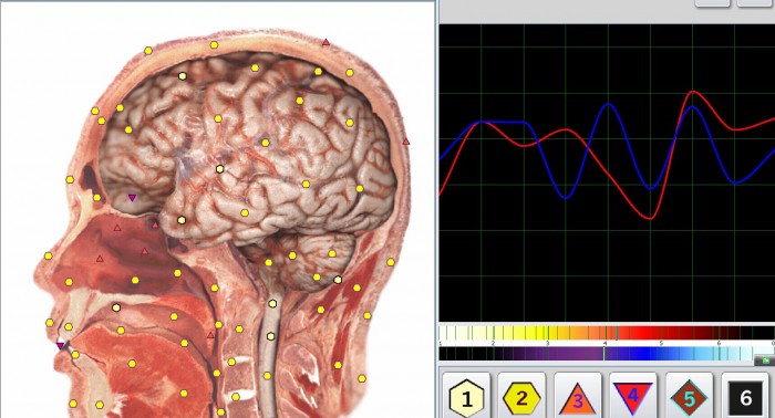
Another possibility of using the apparatus is to
collect the digital signature of an organ as obtained
by the triggering sensor with the library of available
signatures collected previously from normal volunteers.
Such comparison allows determining the degree
of pathology and the state of disease development
of the organ.
Further characterization of the disease state is
possible using the following classification method
developed by the inventors:
Class 0—ideal correlation of the digital signature
of the organ under evaluation with the normal signature
on file. Example—human egg cell at the beginning
of the division process;
Class 1—the tissue of a healthy embryo before
birth (without any body functions or toxins present);
Class 2—the tissue of a healthy newborn at the
beginning of its life outside the mother, tissue functioning
at the beginning stages;
Class 3—actively functioning tissue without toxins
present;
Class 4—tissue with impaired function, toxin accumulation
is just beginning;
Class 5—tissue with organic changes in which
the toxins are accumulated within the cells of the tissue
and actively restrict its function; and
Class 6—extreme and irreversible state of organic
damage and overall tissue disbalance.
Although the invention herein has been described
with respect to a particular embodiment, it is
understood that this embodiment is merely illustrative
of the principles and applications of the present
invention. It is therefore to be understood that numerous
modifications may be made to the illustrative
embodiment and that other arrangements may be
devised without departing from the spirit and scope
of the present invention as defined by the appended
claims.
Magnetic
Induction
Coils
Electromagnetic Impulses
Frequency of Coil Interruptions
Video Monitor
Stimuli
Color
Visual Sequence
Dark Maroon
Red
Orange
Yellow
Green
light Blue
Violet
Dark Violet
Blue
DO
RE
MI
FA
FA-Dies
SOL
SI
DO
LA
1.66
2.49
3.32
4.15
4.56
4.98
6.64
7.47
5.81
1
2
3
4
5
6
8
9
7
Audio (music notes)
Sound
Stereo Headsets
TABLE 1
Peripheral Device-54-
We claim:
1. A biofeedback diagnostic system comprising
a central processing and telemetry unit and a
non-invasive triggering sensor equipped with
a noise generator, said central processing unit
including a situation-generating block for producing
a predetermined series of stimuli, said
central processing unit also including a dual
peripheral means for transmitting said stimuli
in parallel to both an operator and a patient
and therefore forming two biofeedback loops,
consisting of both:
a) a first biofeedback loop including said central
processing and telemetry unit sending said stimuli to
said patient, said triggering sensor for remotely detecting
said patient’s brainwaves representing said
patient’s response to said stimuli, said triggering
sensor further generating a signal in response to said
brainwaves and sending it back to said central processing
unit, and
b) a second biofeedback loop including said central
processing unit sending said stimuli to said operator,
said operator affecting said patient to alter said
patient’s brainwaves, said triggering sensor reflecting
said alteration in said signal back to said central processing
and telemetry unit.
2. The biofeedback diagnostic system as in claim
1, wherein said stimuli is selected from a group
consisting of magnetic, electromagnetic, audio,
and visual stimuli.
3. The biofeedback diagnostic system as in claim
1, wherein said triggering sensor further including
a detector channel equipped with a
logoperiodic antenna to enhance detection of
said patient’s brainwaves.
4. The biofeedback diagnostic system as in claim
3, wherein said logoperiodic antenna is a multi-turn
tapered spiral antenna for short wave
reception at about 1.45 GHz.
5. The biofeedback diagnostic system as in claim
1 further comprising an intuition enhancement
means for assisting the patient in generating
a response to said stimuli.
6. The biofeedback diagnostic system as in claim
5, wherein said intuition enhancement means
including an optoelectronic radioelement and
a light source directed thereon, said radioelement
adapted for placement on a forehead of
said patient.
7. The biofeedback diagnostic system as in claim
6, wherein said radioelement is a silicon-based
field-effect transistor with a control area being
a thin flat channel, said light source being
a laser having the power of less than 5 MW,
said laser controlled to illuminate Said control
area of said radioelement with pulses of light
with the wavelength of between about 630 and
680 nanometers.
8. The biofeedback diagnostic system as in claim
7, wherein said pulses of light having a frequency
coinciding with the patient’s brainwaves
theta-rhythm.
9. The biofeedback diagnostic system as in claim
8, wherein said intuition enhancement means
further including a cavity resonator to block
the electromagnetic component of said pulses
of light while permitting the torsion components
thereof to reach the patient.
10. The biofeedback diagnostic system as in
claim 9, wherein said cavity resonator having
a volumetric chamber with the size being
a multiple of the wavelength of about
1.45 GHz.
11. The biofeedback system as in claim 1, wherein
said central processing and telemetry unit
further comprising a designation block for
assigning specific relative weights to said signals
from said triggering sensor.
We are MAIKONG 3d nls health analyzer | 3d nls health analyzer price | Metatron 4025 Hunter | original 3d DIACOM nls|www.3d-nls-health-analyzer.com,manufacturers Unified Wholesale price.Welcome to inquiry and OEM.
Related Items